The Global
Information Hub for
Lighting Technologies
and Design
Schematic diagram of LED with backside reflector composed of TiO2/Al2O3 DBR and Al mirror grown on backside of PSS. Insets: SEM images of fabricated DBR and PSS (Figure 1). LOP of fabricated LEDs versus injection current(a). Inset: electroluminescence spectra. Photographs of LEDs (b and c) with and without backside reflector in operating state, respectively (Figure 2)https://zmi.led-professional.com/Plone/media/technology_light-generation_new-atomic-layer-deposition-process-for-nitride-led-reflector-structures_Schematic%20diagram%20of%20LED%20with%20backside%20reflector.jpg/viewhttps://zmi.led-professional.com/Plone/media/technology_light-generation_new-atomic-layer-deposition-process-for-nitride-led-reflector-structures_Schematic%20diagram%20of%20LED%20with%20backside%20reflector.jpg/@@images/image-1200-421696e858fda0c4d328f3ccbd265b07.jpeg
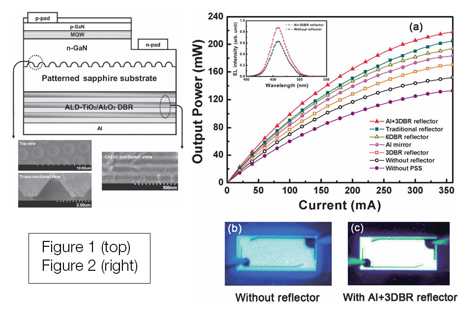
Schematic diagram of LED with backside reflector composed of TiO2/Al2O3 DBR and Al mirror grown on backside of PSS. Insets: SEM images of fabricated DBR and PSS (Figure 1). LOP of fabricated LEDs versus injection current(a). Inset: electroluminescence spectra. Photographs of LEDs (b and c) with and without backside reflector in operating state, respectively (Figure 2)
. LOP of fabricated LEDs versus injection current(a). Inset: electroluminescence spectra. Photographs of LEDs (b and c) with and without backside reflector in operating state, respectively (Figure 2)")
